
86-755 0755-84501787
Author:Jessie Time:2024-05-20 Browse:
Closed Loop Stepper motor Hybrid Integrated Stepper Servo Motor driver apply for sewing machine,Textile Machine,jacquard Machine,Embroidery Machine and all kinds of CNC machines.
一、Product Specification
The LT-PM02NXX series closed-loop servo motor is used for high-precision closed-loop motor products. The closed-loop servo motor has a specific remote communication function, which can achieve automation, remote control, and intelligence of motor control.
This document applies to closed-loop servo motors of LT-PM02N02, LT-PM02N03, LT-PM02N04, and LT-PM02N05.
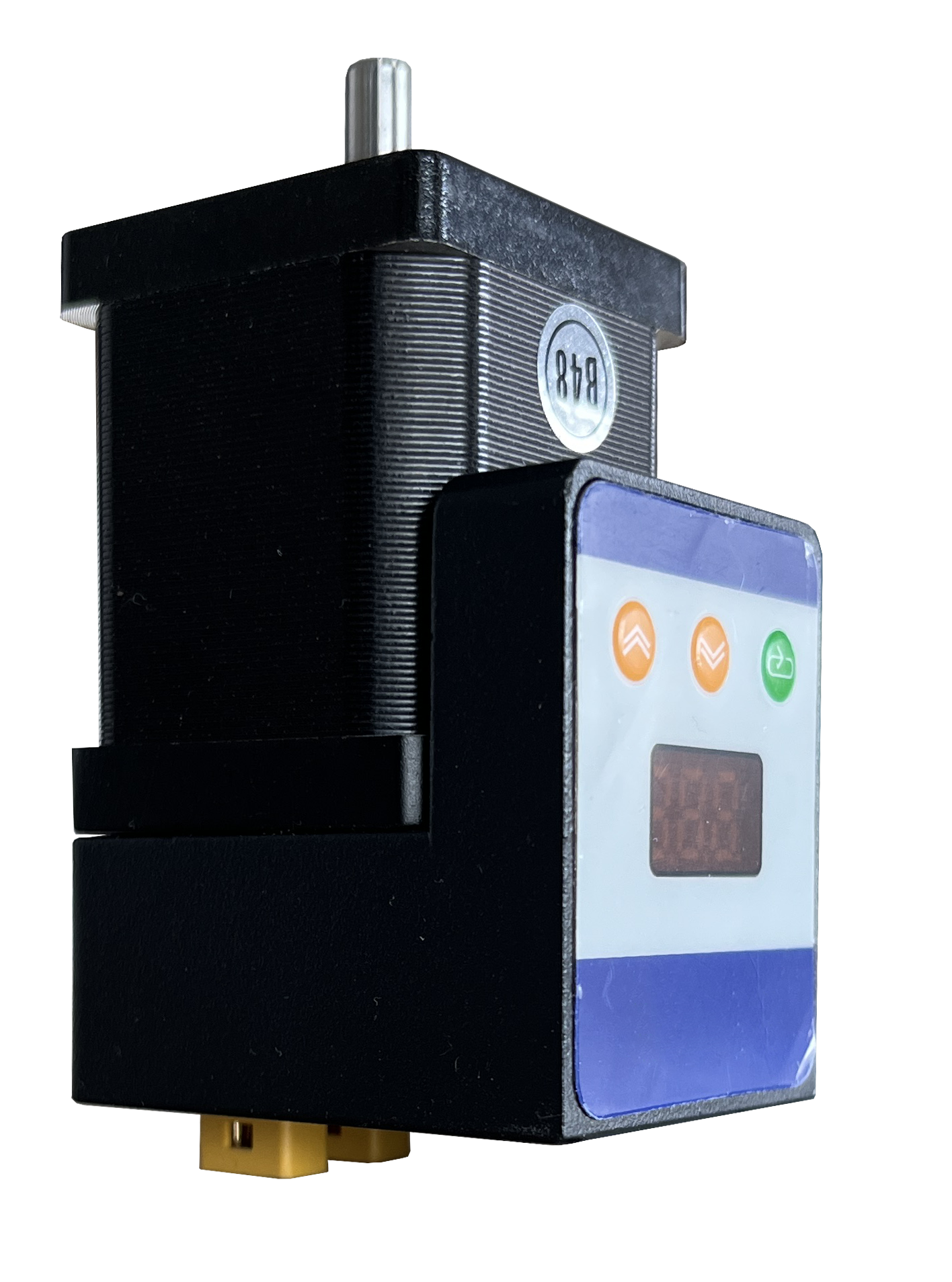
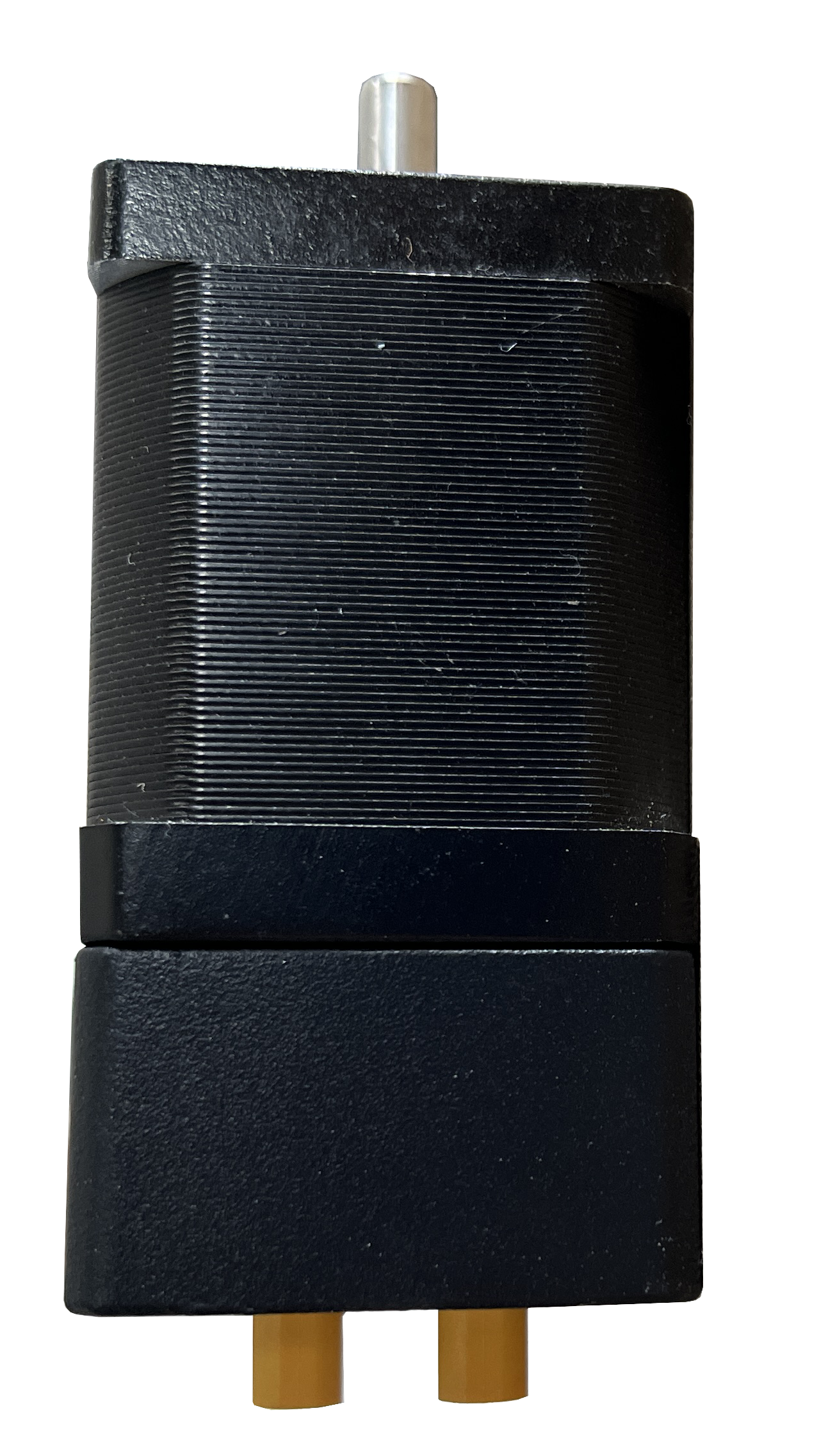
二、Product rendering
According to the type of motor and installation method, it can be divided into the following models:
1. The motor type of LT-PM02N02 closed-loop servo motor is 42 motor, and the installation method is horizontal installation:
2. The motor type of LT-PM02N04 closed-loop servo motor is 42 motor, and the installation method is vertical installation
3. The motor type of LT-PM02N05 closed-loop servo motor is 35 motor, and the installation method is horizontal installation
4.The motor type of LT-PM02N03 closed-loop servo motor is 35 motor, and the installation method is vertical installation
三、Function Description
1. Closed loop feedback function
Using absolute position sensors can real-time sensing the position inf of the motor, ensuring that the position of the motor is consistent with the control position.
2. Zero-adjustment function
Support setting any position to Zero
3. Power outage memory function
Support power-off memory of the last operating position information, and automatically restore to the corresponding position when powered on again.
4. High precision positioning function
By using high precision driver chips and connecting with the jacquard system, high-precision positioning can be achieved.
5. Serial interconnection function
By using bus connection, multiple closed-loop servo motors can be connected and used together.
6. Abnormal alarm function
Supporting multiple abnormal alarms, the system can perceive the working condition of the motor in real time
7. Parameter setting function
Support local and remote settings to achieve information such as device address, zero position, speed, torque, etc.
四、Characteristics and Tech Specification
1. Characteristics
The product has the following characteristics:
(1)Has a large torque output, and the output torque can be adjusted as needed;
(2)High positioning accuracy, with 1024 line high-precision encoder chip installed internally, suitable for high-precision control equipment:
(3)The angle is automatically corrected, and it can be automatically corrected in case of angle deviation.
2. Tech Specification
The main technical Specification of the product are as follows:
(1)Power supply voltage:DC 24V;
(2)Communication interface type: CAN interface, transmission rate 1MHz;
(3) Motor rotation direction: supports custom rotation direction;
(4)Rotation angle range:-350 °~+350 ° ;
(5)Angle correction range:2.0 °~7.0 °(Automatically correct when angle shift is caused by machine vibration);
(6)Angle error alarm:>7.0 °(If the error exceeds this value, an alarm prompt will be triggered)
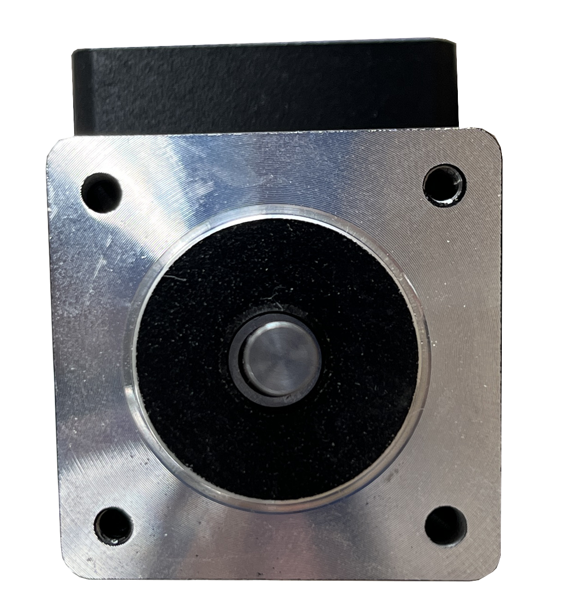
五、Running direction
From the front view, the output shaft of the closed-loop servo motor rotates counterclockwise (CCW) as a forward rotation (as shown in pic 3)
Rotate CW clockwise (clockwise) to reverse

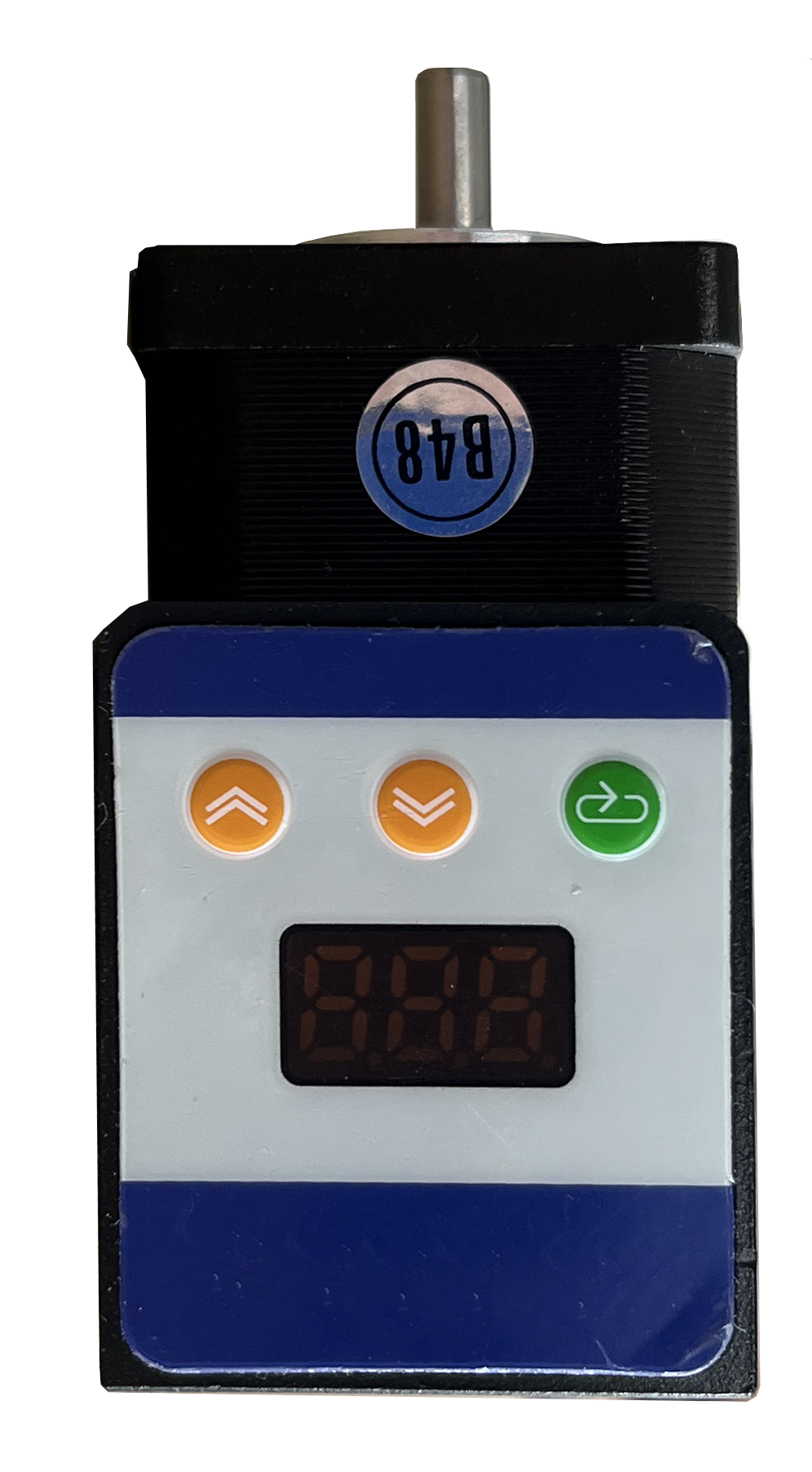
六、Menu and Keypad
1. Digital tube display
Using a digital display, the position information is displayed under normal circumstances. If you long press [Settings], the corresponding menu information will be displayed.
2. Menu options
Supports four menu setting options (P1~P7), see below definitions:
(1)P1:Device address, representing the communication address of this device, with a setting range of 1-250;
(2)P2:Installation method selection, means the installation method of this device, 0 represents "A" or 1 represents "B" installation
(3)P3:Zero setting: Short press the [+] button on the zero position setting parameter interface to move forward one step, long press the [+] button to move forward continuously .same rule for(-) button,Simultaneously display rotating icons,The specific zero position is based on the motor's operating position (recommend to use this method to set the zero position);
(4)P4:Running speed, adjusting the speed of the motor during operation, setting levels 1-10 (default value 6)
(5)P5:Operating torque, adjust the size of motor operating torque, set levels 1-10 (default value 6);
(6)P6:Maintain torque, adjust the motor to maintain torque, set levels 1-10 (default value of 6)
(7)P7:Language, indicating the language type of menu operation, supporting switching between Chinese and English;
Note 1:When setting parameter, remote communication with this device must be stopped first to prevent interference with the zero point setting.
Note 2;Once complete zero position adjustment, press [Set] button for 2 seconds to set the current position to zero
3. Key Function Description
The closed-loop servo motor provides three buttons, Below are definitions
(1)【Setting】:Long press,Press and hold for 2 seconds to enter the parameter setting interface. After setting the parameter values, press and hold for 2 seconds again to save the parameters; Short press to switch between menu and parameter items;
(2)【+】;Parameter value increases
(3)【-】;Parameter value decrease
Note;In the parameter setting interface, if there are no button operations for 60 seconds, the timeout will automatically return to the main interface (parameters will not be saved)
七、Remote Operation
1. Remote to modify Address
The address of this device can be remotely modified through the system within the first 20 seconds of each power on of the closed-loop servo motor. After the device automatically goes online after this time, remote modification of the device address is no longer allowed.
The system remotely modifies the device address, and the jacquard system tests the motor (Test ->Motor ->Single ->Address ->(Upper/Lower Disk) ->Address Positioning) as shown in pic4.

After completing the operation as shown in the above diagram, power on the closed-loop servo motor that needs to modify its address separately
Note:This operation should be used with caution. If the address is changed or the device is turned on for more than 20 seconds, it will automatically go online.
2. Remote zero position recognition
Run the motor to the corresponding position through testing, and then perform zero position recognition (testing ->motor ->single/all ->set address (single valid) ->upper/lower panel ->zero position recognition). The schematic diagram of zero position recognition is shown in Pic 5.

Once complete operation, the current position can be set to zero. Due to its relatively complex operation, Not recommended to use this method to set the zero position
3. Running tests
Test the jacquard system motor (test ->motor ->all ->test value 300->(upper/lower plate) ->start testing), check the operation of the motor, ensure that all motors are running normally, and the configuration interface is shown in pic #6

4. Running direction
(1)All devices are powered on, and the jacquard system is set (parameters ->system ->enable density motor). The interface is shown in Pic# 7

(2)Set the direction of motor operation, jacquard system settings (parameters ->jacquard ->general ->(lower/upper) density motor direction), interface as shown in Pic# 8

INTERFACE
Table 1 Definition of Power Interface


INSTALLATION DIAMENSIONS


SYSTEM CONNECTION DIAGRAM
diagram is shown in pic 11

Common Errors
Table 3 Common Failed Display

Specification


Previous Article:No More!
Next Article:No More!
 Contact Us:86-755 0755-84501787
 Mailbox:jessie@szlitus.com
 Headquarters Address:1808, Building A, Rongde International, Henggang Street, Longgang District, Shenzhen


Skype
Copyright © 2005-2023Shenzhen Lites Electronic Technology Co., Ltd All Rights Reserved Record number: Guangdong ICP backup2024178703-1 Background login
 CN
CN EN
EN

 Download